BUILDING INSTRUCTIONS
STEP 0: OUR RECOMMENDED STRUCTURE
The following instructions show how to build the recommended module structure:SeparatorPrechamber + HeatExchangerSegment + SeparatorPrechamber
If you want to build something else that is not intuitively obvious, please feel free to ask us for advice. Of course, this also applies in general: if you should need help, don't hesitate to CONTACT US : )
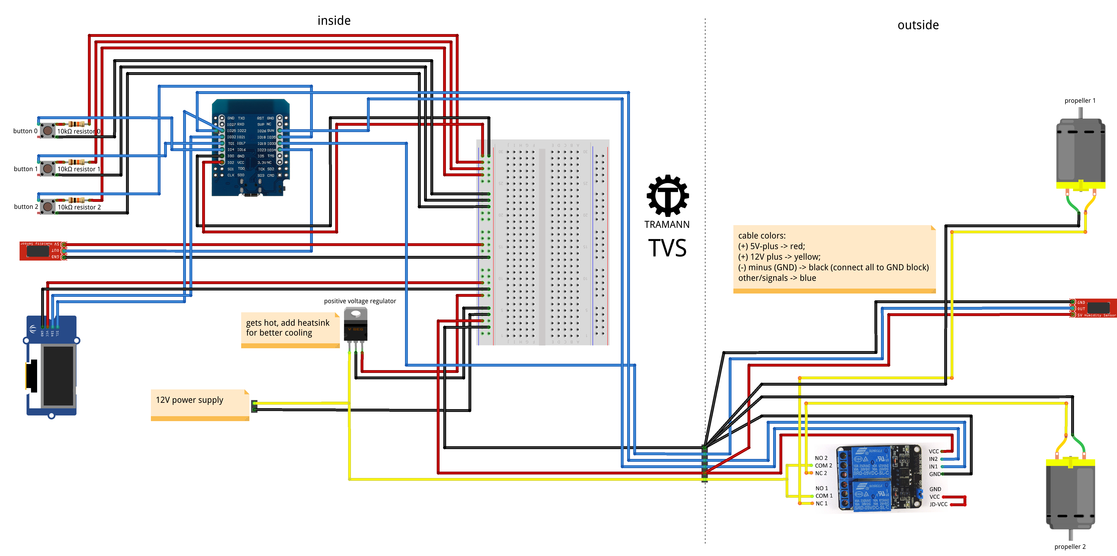
STEP 1: PREPARATIONS AND SOURCING
Make sure, that you have a 3D-printer (if you shouldn't have one, maybe ask a friend (if you shouldn't have one, maybe try to make some friends) or visit our TRAMANN SHOP).If you haven't already, please take a look at the requiered PARTS, scroll down to ADDITIONAL PARTS and buy them. If you shouldn't be able to get something from that list, again try friends or visit our TRAMANN SHOP.
STEP 2: PRINTING PARTS
Please print the following PARTS.>> DOWNLOAD STL-MODEL OF THE SEPARATOR PRECHAMBER (you will need it twice)
>> DOWNLOAD STL-MODEL OF THE FILTER HOLDER DUO
>> DOWNLOAD STL-MODEL OF THE INTERIOR COVER PLATE
>> DOWNLOAD STL-MODEL OF THE EXTERIOR COVER PLATE
>> DOWNLOAD STL-MODEL OF THE EXTERIOR PROTECTIVE FILTER (you will need it twice)
>> DOWNLOAD STL-MODEL OF THE SEPARATOR BACKCHAMBER, PART 1 (you will need it twice)
>> DOWNLOAD STL-MODEL OF THE SEPARATOR BACKCHAMBER, PART 2 (you will need it twice)
>> DOWNLOAD STL-MODEL OF THE SEPARATOR BACKCHAMBER, PART 3 (you will need it twice)
STEP 3: START ASSEMBLING
Please assemble the heat exchanger first, by taking the PVC tube and the straws and connecting them with part 1 und part 2 of the separator backchamber. Fixate everything with the threaded rod and the two corrensponding nuts. Now add part 3 of the separator backchamber, but only on one side and then connect the first separator prechamber, the exterior cover plate, the two propellers and the two exterior protective filters. This will be the first segment, now we build the second segment, but we won't connect them yet, because we still need to put the first segment throught the wall. For the second segment, connect the second separator prechamber with the filter holder.STEP 4: INSTALLING ELECTRONICS
Please refer to the diagram below for the wiring of the electronic components.
STEP 5: CONFIGURING ESPHOME AND CONNECTING WITH HOME ASSISTANT
If you haven't already, please install the addon for ESPHome in the Home Assistant Store for free. After that you have to click on - Start - to start running ESPHome and navigate to - ESPHome - in the menu on the left side of your screen. Connect the ESP32 to your computer and create a new device. Follow the instructions in the web installer, install over - Plug into this computer - this time and from now on you can also update - Wirelessly - over your WLAN.After the installation you can open the current source code of your new ESPHome device by clicking on - edit - and replace it with the TVS source code.
Please install the new code on your ESP32 by clicking on - install- in the top right corner of your screen. Now copy the API-key from the source code, go to - settings - in Home Assistant, navigate to - devices and services - and then to the new - ESPHome -, click on - configurate -, paste the API-key and send the form.
STEP 6: CORE DRILLING
The TVS needs a hole with at least a diameter of 125mm in your wall. If you are just replacing an old ventilation system, maybe you can reuse the existing hole or you can use a small window, for example at your attic. If you shouldn't already have an existing hole somewhere, you need to drill a new one.You can either hire a professional or do it yourself with your own core drill or borrow one. It's best to take a look at a few tutorials on the internet before you start drilling. If possible, drill with a slight incline (only a few degrees) so that it goes slightly downwards from the inside to the outside, so that potential drainage water would run outside. This may all sound a bit daunting, but it is feasible and if you have made a mistake, in our experience the hole can certainly be plugged again.
STEP 7: FINISH ASSEMBLING
Now put the first segment througt the wall, connect it with the second part 3 of the separator backchamber, with the second segment and with the interior cover plate.STEP 8: OPERATION AND MAINTENANCE
Congratulations! You made it, your TVS should now be working! We are very proud of your accomplishment!As standard, the device supports three different modes: manual mode (control the device manually by pressing the button, turn on for 20 minutes and then resume to automatic mode), automatic mode (the device decides independently, based on measured values and formulas (this setting is default and recommended)) and programmed mode (if you want, you can insert your own code here to program the device yourself) You can switch between the modes by pressing the corresponding buttons and the currently selected mode is displayed in the top right-hand corner of the screen.
Now we recommend to change the filters approximately every six to eight months, (it's probably best to write that in your calender right now, so you won't forget).
Furthermore, if you are having questions, feedback, ideas, need for support, suggestions, something else?
Always feel free to CONTACT US : )